Have you ever key-ed up your handheld radio, ready to ask a friend across town how their day is, and then paused, paralyzed by the cryptic instructions on your radio’s screen or the unfamiliar terms you hear on the air? The world of amateur radio, or “ham” radio, is full of exciting possibilities, but it can also be a maze of technical jargon. Fear not, fellow operator! Today, we’re pulling back the curtain on one of the most fundamental concepts in our hobby: Simplex versus Duplex, or the fascinating world of repeaters.
Take a look at this detailed infographic we’ve put together. It’s designed to make these core concepts crystal clear, but sometimes a visual guide is even better with a companion explanation. Let’s break it down, section by section, starting with the simplest form of communication.
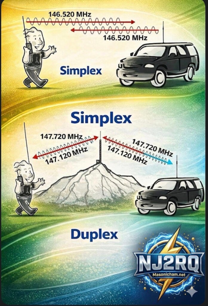
Figure A: The Simplex – When Simple is Best
Think of the Simplex pattern, shown on the far left of the diagram, as a focused flashlight beam in the pitch-black night. It’s direct, straightforward, and covers a wide area for local communication.
Here, we’re comparing it specifically to a simple dipole antenna—the oldest and most common type of antenna in the ham radio world. The pattern itself, that large “Figure-8” you see in Figure A, is a 2D slice of how the energy radiates from that horizontal wire. It’s called an “Omnidirectional (Horizontal)” pattern, often described as a “Doughnut Shape.”
What does this mean for you as an operator?
This pattern is excellent for broad, local communication because your energy is radiated almost equally in every direction away from the axis of the antenna. You don’t need a massive, rotating antenna tower or a highly-tuned beam to make successful local contacts on the 2m or 70cm bands. This is also the fundamental behavior of every dipole antenna, making it the bedrock of antenna design. But as the text notes, because it’s so “forgiving” and spreads that energy out over a vast 360-degree area, your signal becomes relatively weak by the time it reaches a very distant receiver. To reach over greater distances with less power, we need to get more directional.
Sculpting the Pattern: Dipole VS. Beam
The central panel shows the transition. We can take that basic, spread-out dipole pattern and “sculpt” it by adding a few carefully calculated passive elements. This creates the pattern on the right: a highly-focused directional beam, which acts more like a high-intensity laser than a broad flashlight.
As illustrated, adding a simple reflector element behind the original dipole element (which is now the “driven element”) and perhaps a few smaller director elements in front of it will dramatically change how the energy behaves. The 3-element Yagi beam on the right, for example, is a classic design that achieves this transformation. You focus and redirect that otherwise wasted energy from the back and sides, concentrating it all into one powerful lobe of gain.
Figure B: The Yagi Beam – Focus and Gain for the Real-World Advantage
This brings us to the most complex and exciting part of the chart: Figure B, the Yagi Directional Pattern. Here, that same energy is now shaped into a main, powerful lobe pointing directly at your target. But that focus comes with complexity, creating several distinct lobes that every operator should understand:
• MAIN LOBE: This is your best friend. It is the peak concentration of all your focused power. When propaganda conditions are tough, this is the lobe that can punch your signal through to that rare DX contact.
• GAIN: This is the practical advantage that all this focus buys you. It’s measured in decibels (dB) and essentially represents how much “louder” you appear to the other station compared to that reference dipole we started with. More gain is almost always better for overcoming noise or distance.
• BACK LOBE (REJECTION): The mirror image of the main lobe, but often much smaller. Good antenna designs minimize this to prevent picking up unwanted noise or interfering signals from the wrong direction. The goal is to maximize “REJECTION,” making your antenna blind to signals from behind.
• SIDE LOBES (MINIMIZED): These are like secondary beams that point in unwanted directions. Just like back lobes, a high-quality antenna will minimize these to optimize efficiency.
• F/B RATIO (Front-to-Back): This is a critical measurement. A ratio like 20+ dB, as noted, means your main signal is 20 dB (or 100 times!) stronger than the signal coming in from the exact opposite direction. This is the difference between a clear, one-on-one contact and a chaotic interference fest.
• F/S RATIO (Front-to-Side): Similar to the F/B ratio, but measured against the side lobes. It tells you how effective the antenna is at filtering out noise and other stations that are off-axis to your main direction. A high F/S ratio makes for a quieter, more focused receiver.
The Real-World Connection: Hamradio Operator QTH A to QTH B
Finally, the bottom of the infographic puts these abstract concepts into a real-world scenario. Two operators, HAMRADIO OPERATOR (QTH A) and HAMRADIO OPERATOR (QTH B), are trying to connect over a challenging distance.
When the propagation is tricky (maybe the solar flux is low), simply pointing their high-gain Yagi beams at each other (the “Doughnut Shape” versus the “laser focus”) can make all the difference. Their 3D multi-petal beam visualization illustrates how they are sculpting the ideal propagation path with focused energy to maximize their odds of a successful contact. It’s not just about raw power; it’s about smart, efficient design.
The Bottom Line:
An infographic like this is a powerful visual reminder that as ham radio operators, we’re not just users of technology—we’re engineers of our own signals. By understanding these concepts and using the right tools, whether it’s the simplicity of a dipole or the surgical precision of a high-gain beam, you can make smarter decisions, overcome limitations, and truly unlock the potential of your radio setup.
What kind of antenna patterns are you using at your station? Share your experiences in the comments below, and let’s keep the discussion focused and forward-looking.