In our last post, we explored how the ionosphere is a moving, shimmering curtain that creates signal fluctuations like QSB and Fading. But understanding propagation is only half the battle. To effectively communicate on the HF bands, you also need to understand your Antenna Radiation Pattern. This pattern is essentially a blueprint of where your antenna sends (or receives) energy.
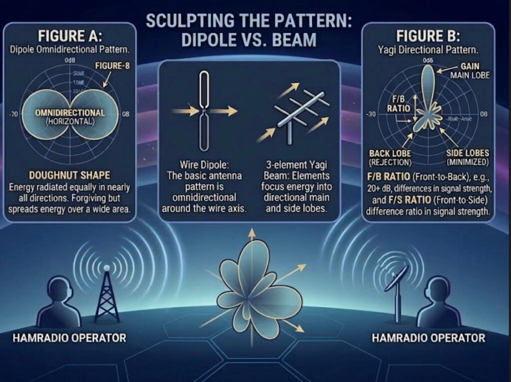
Let’s look at this comparison diagram to visualize why a dipole in your backyard behaves so differently from a large multi-element Yagi beam.
The Power of Focus: Omindirectional vs. Directional
An antenna’s pattern is a 3D plot of its relative field strength. This diagram simplifies it into a horizontal 2D slice, which is perfect for understanding directional gain.
1. The Omnidirectional “Doughnut” (Figure A – Dipole)
The pattern on the left is typical of a horizontally oriented dipole antenna.
• What it means: Energy is radiated broadly in nearly all directions. It is “omnidirectional” in the horizontal plane (forming a doughnut shape around the wire).
• The Takeaway: This is excellent for general operating and making contacts without needing to rotate your antenna. It’s forgiving, but it spreads your energy thin over a vast area.
2. The Directional “Flashlight” (Figure B – Beam)
The pattern on the right shows a high-gain directional antenna, like a Yagi or quad loop array. Notice how the energy isn’t just a circle; it’s sculpted into distinct lobes.
• The Main Lobe: This is where the majority of your energy is focused. It acts like a powerful flashlight beam, concentrating power in one specific direction.
• The Back and Side Lobes: This is “wasted” or secondary energy radiating in directions you aren’t trying to target. High-quality antenna designs minimize these to maximize the main lobe.
• The Gain Effect: By focusing your 100 watts into that narrow main lobe instead of a big omnidirectional doughnut, your signal “appears” many times stronger at the distant receiving station. This is called antenna gain.
3. Front-to-Back (F/B) and Front-to-Side (F/S) Ratios
A key specification for any directional antenna is how well it rejects signals from the sides and back.
• F/B Ratio: This is the difference in signal strength between the peak of the Main Lobe (front) and the peak of the Back Lobe. A high ratio (e.g., 20+ dB) means that weak stations behind you will be much quieter, helping you focus on the station you are aiming for.
• F/S Ratio: Similarly, this is the difference between the main lobe and the Side Lobes. It tells you how effective the antenna is at “ignoring” noise or interference from directions other than your primary target.
Your Signal is a Laser, Not a Floodlight
Thinking about your antenna pattern is crucial. When propagation is challenging, a few extra dB of focused gain from a directional antenna can be the difference between a successful QSO and vanishing into the noise.